100mm Aerodynamic Propulsion System (Ducted Fan Assembly)
About this project
Project Overview This project features the complete design and parametric optimization of a high-efficiency 100mm Ducted Fan Propulsion System engineered for UAV and VTOL applications. Designed in SolidWorks, the assembly prioritizes streamlined airflow, structural rigidity, and tight mechanical tolerances across rotating and stationary components. Key Technical Features • Optimized Inlet & Shroud Geometry: Features a prominent 20mm radius elliptical bell-mouth inlet to minimize boundary layer separation, transitioning into a rigid 5mm constant-wall section and a converging exit nozzle to accelerate thrust velocity. • Aerodynamic Tail Cone: A 50mm tall tail cone defined by a smooth 130mm radius curve to reduce wake turbulence and drag at the exhaust exit. • Precision Fit & Clearance: Engineered with a 4.00mm radius (8mm diameter) bore on rotating parts (Rotor Hub & Nose Cone) for secure shaft mounting, paired with a 4.50mm radius bore on stationary components (Stator Pod & Tail Cone) to maintain a frictionless 0.50mm air gap. • Structural Stator Stage: Integrates 2.00mm thick exit guide vanes to bridge the core pod to the main duct while removing airflow swirl to maximize directional force. Software & Methods • CAD Software: Dassault Systèmes SolidWorks • Techniques: In-Context Assembly Modeling, Parametric Surface/Solid Lofting, Circular Patterning, Mechanical Fit Optimization Full case study available on Behance: https://www.behance.net/gallery/255227805/100mm-Propulsion-System-(Ducted-Fan-Assembly)
Files
6 Files
Sign in to view this file
Viewing files on ForgeHub is free. Sign in or create an account to open the interactive viewer and download files.
Sign in to viewActivity
Related Projects
Iron Dome "Intercept" Algorithm: Scaled Simulation
Vikram Singh
Sep 16, 2026
Rubble Survivor Detection Drone
Felix Moreno
Sep 16, 2026
FEA‑Based Optimization of Cylindrical Support
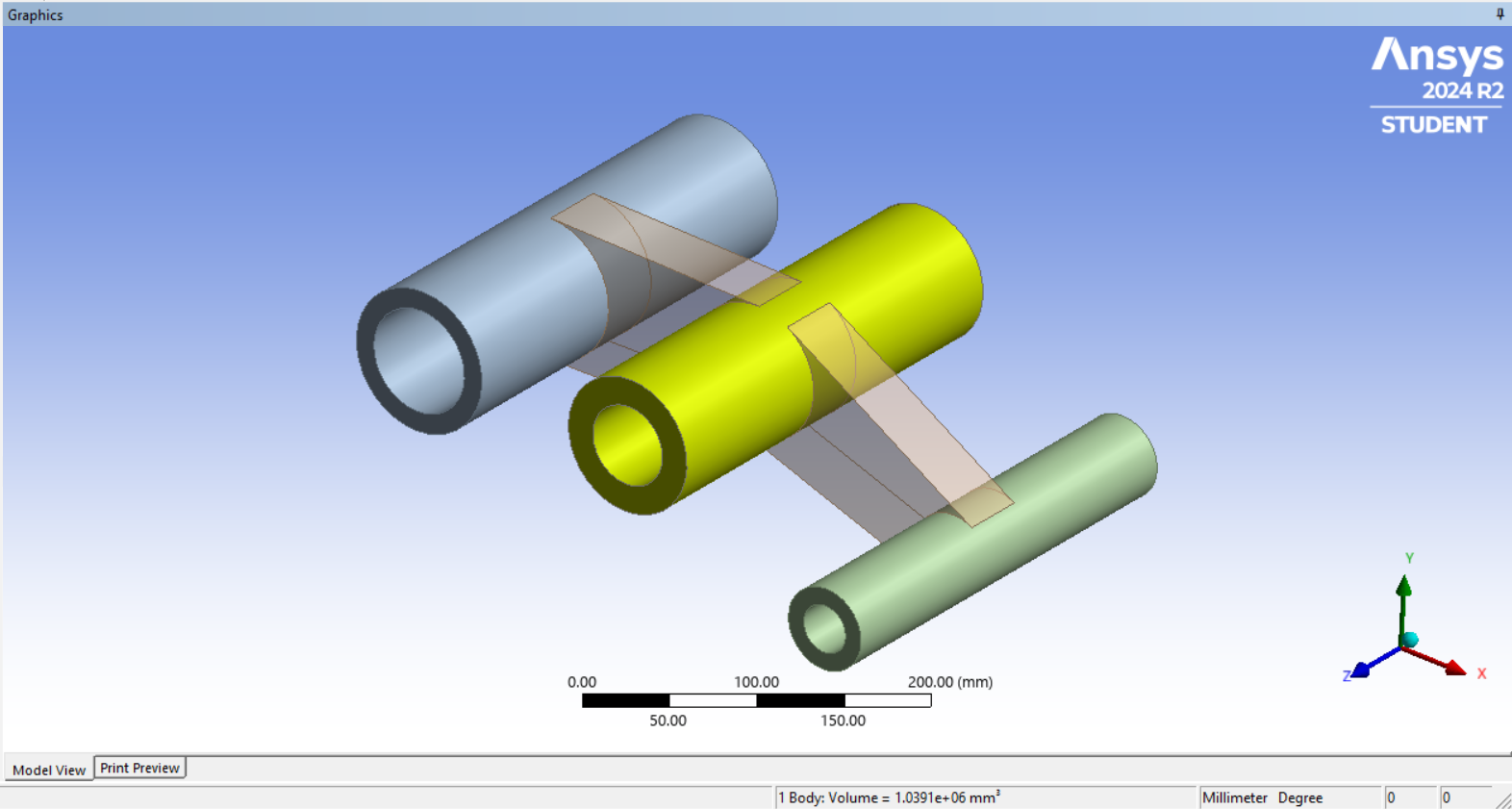
This project applies Finite Element Analysis (FEA) and response‑surface‑based optimization to redesign a steel cylindrical support subjected to a 12 kN bearing load. Using ANSYS Workbench, the study evaluates how varying the web thickness influences structural stress and total mass. A Central Composite DOE and second‑order response surface were used to model the relationship between thickness, von Mises stress, and mass. Optimization was performed with a constraint of ≤35 MPa allowable stress. Results show a clear trade‑off: thinner designs reduce mass but exceed stress limits, while thicker designs improve strength at the cost of weight. The optimal solution was found at 24.25 mm thickness, achieving 33.16 MPa stress and 23.38 kg mass, satisfying safety requirements while minimizing material usage. This project demonstrates practical skills in FEA, parametric modelling, DOE, response surface methodology, and structural optimization, delivering a lightweight and structurally efficient design. Full case study available on Behance: https://www.behance.net/gallery/255252331/FEA-Based-Optimization-of-Cylindrical-Support

Jayant Gosavi
Sep 3, 2026